- 您现在的位置:买卖IC网 > Sheet目录989 > MAX16802BEVKIT (Maxim Integrated Products)EVAL KIT FOR MAX16802
�� �
�
�Offline� and� DC-DC� PWM� Controllers� for�
�High-Brightness� LED� Drivers�
�When� in� the� bootstrapped� mode� with� a� transformer�
�(Figure� 5),� the� circuit� is� protected� against� most� output�
�short-circuit� faults� when� the� tertiary� voltage� drops�
�below� +10V,� causing� the� UVLO� to� turn� off� the� gate�
�drive� of� the� external� MOSFET.� This� re-initiates� a� startup�
�sequence� with� soft-start.�
�When� the� LED� current� needs� to� be� tightly� regulated,� an�
�internal� error� amplifier� with� 1%� accurate� reference� can�
�be� used� (Figure� 9).� This� additional� feedback� minimizes�
�the� impact� of� passive� circuit� component� variations� and�
�tolerances,� and� can� be� implemented� with� a� minimum�
�number� of� additional� external� components.�
�A� wide� dimming� range� can� be� implemented� using� a�
�low-frequency� PWM� dimming� signal� fed� directly� to� the�
�DIM/FB� pin.�
�LED� driver� circuits� designed� with� the� MAX16801� use� a�
�high-value� startup� resistor� R1� that� charges� a� reservoir�
�capacitor� C1� (Figure� 5� or� Figure� 9).� During� this� initial�
�period,� while� the� voltage� is� less� than� the� internal� boot-�
�strap� UVLO� threshold,� the� device� typically� consumes�
�only� 45μA� of� quiescent� current.� This� low� startup� current�
�and� the� large� bootstrap� UVLO� hysteresis� help� minimize�
�R1�
�the� power� dissipation� across� R1,� even� at� the� high� end�
�of� the� universal� AC� input� voltage.�
�An� internal� shutdown� circuit� protects� the� device� when-�
�ever� the� junction� temperature� exceeds� +130°C� (typ).�
�Dimming�
�Linear� dimming� can� be� implemented� by� creating� a�
�summing� node� at� CS,� as� shown� in� Figures� 6� and� 7.�
�Low-frequency� PWM� (chopped-current)� dimming� is�
�possible� by� applying� an� inverted-logic� PWM� signal� to�
�the� DIM/FB� pin� of� the� IC� (Figure� 8).� This� might� be� a� pre-�
�ferred� way� of� dimming� in� situations� where� it� is� critical� to�
�retain� the� light� spectrum� unchanged.� It� is� accom-�
�plished� by� keeping� constant� the� amplitude� of� the�
�chopped� LED� current.�
�MAX16801/MAX16802� Biasing�
�Implement� bootstrapping� from� the� transformer� when� it�
�is� present� (Figure� 5).� Biasing� can� also� be� realized�
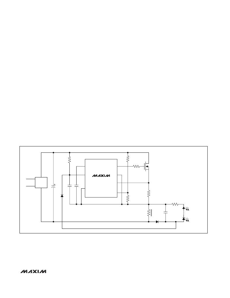
�directly� from� the� LEDs� in� non-isolated� topologies�
�(Figure� 1).�
�Bias� the� MAX16802� directly� from� the� input� voltage� of�
�10.8VDC� to� 24VDC.� The� MAX16802� can� also� be� used�
�R5�
�R2�
�V� CC�
�IN�
�NDRV�
�GND�
�Q1�
�AC�
�IN�
�BRIDGE�
�RECTIFIER�
�C1�
�C2�
�C3�
�COMP�
�MAX16801B�
�CS�
�DIM/FB�
�UVLO/EN�
�R6�
�R3�
�R4�
�L1�
�C4�
�TOTAL� LED� VOLTAGE:�
�11V� TO� 23V�
�D3�
�Figure� 1.� Biasing� the� IC� using� LEDs� in� Nonisolated� Flyback� Driver�
�_______________________________________________________________________________________�
�7�
�发布紧急采购,3分钟左右您将得到回复。
相关PDF资料
MAX16803EVKIT+
EVAL KIT FOR MAX16803
MAX16806EVMAXQUSB+
EVAL KIT FOR MAX16806
MAX16807EVKIT+
EVAL KIT FOR MAX16807
MAX16809EVKIT+
EVAL KIT FOR MAX16809
MAX16814EVKIT+
KIT EAL FOR MAX16814
MAX16816EVKIT+
KIT EVAL FOR MAX16816 LED DRIVER
MAX16818EVKIT+
KIT EVALUATION FOR MAX16818
MAX16820EVKIT+
EVAL KIT FOR MAX16820
相关代理商/技术参数
MAX16803ATE/V+
功能描述:LED照明驱动器 350mA HB LED Drvr w/PWM Dim and 5V Reg RoHS:否 制造商:STMicroelectronics 输入电压:11.5 V to 23 V 工作频率: 最大电源电流:1.7 mA 输出电流: 最大工作温度: 安装风格:SMD/SMT 封装 / 箱体:SO-16N
MAX16803ATE/V+T
功能描述:LED照明驱动器 350mA HB LED Drvr w/PWM Dim and 5V Reg RoHS:否 制造商:STMicroelectronics 输入电压:11.5 V to 23 V 工作频率: 最大电源电流:1.7 mA 输出电流: 最大工作温度: 安装风格:SMD/SMT 封装 / 箱体:SO-16N
MAX16803ATE+
功能描述:LED照明驱动器 350mA HB LED Drvr w/PWM Dim and 5V Reg RoHS:否 制造商:STMicroelectronics 输入电压:11.5 V to 23 V 工作频率: 最大电源电流:1.7 mA 输出电流: 最大工作温度: 安装风格:SMD/SMT 封装 / 箱体:SO-16N
MAX16803ATE+T
功能描述:LED照明驱动器 350mA HB LED Drvr w/PWM Dim and 5V Reg RoHS:否 制造商:STMicroelectronics 输入电压:11.5 V to 23 V 工作频率: 最大电源电流:1.7 mA 输出电流: 最大工作温度: 安装风格:SMD/SMT 封装 / 箱体:SO-16N
MAX16803EVKIT
制造商:Maxim Integrated Products 功能描述:HIGH-VOLTAGE, 350MA, HIGH-BRIGHTNES - Bulk
MAX16803EVKIT+
功能描述:LED 照明开发工具 MAX16803 Eval Kit RoHS:否 制造商:Fairchild Semiconductor 产品:Evaluation Kits 用于:FL7732 核心: 电源电压:120V 系列: 封装:
MAX16803EVKIT+BJT
功能描述:LED 照明开发工具 RoHS:否 制造商:Fairchild Semiconductor 产品:Evaluation Kits 用于:FL7732 核心: 电源电压:120V 系列: 封装:
MAX16804ATP+
功能描述:LED照明驱动器 350mA HB LED Drvr w/analog & PWM Dim RoHS:否 制造商:STMicroelectronics 输入电压:11.5 V to 23 V 工作频率: 最大电源电流:1.7 mA 输出电流: 最大工作温度: 安装风格:SMD/SMT 封装 / 箱体:SO-16N